
Deciphering the Honda B-Series MAP Sensor Wiring: A Comprehensive Guide
Related Articles: Deciphering the Honda B-Series MAP Sensor Wiring: A Comprehensive Guide
Introduction
In this auspicious occasion, we are delighted to delve into the intriguing topic related to Deciphering the Honda B-Series MAP Sensor Wiring: A Comprehensive Guide. Let’s weave interesting information and offer fresh perspectives to the readers.
Table of Content
Deciphering the Honda B-Series MAP Sensor Wiring: A Comprehensive Guide
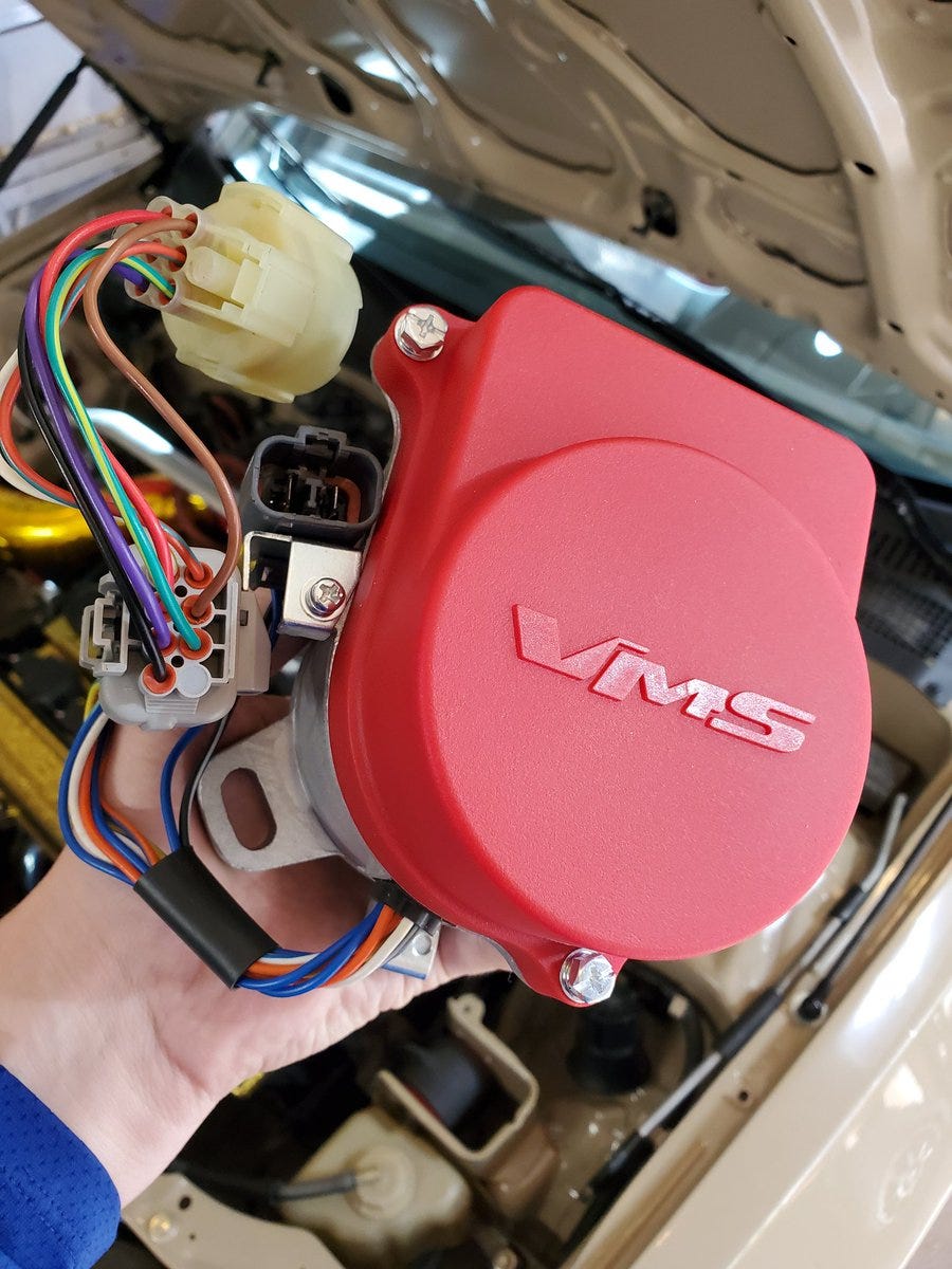
The manifold absolute pressure (MAP) sensor is a crucial component in the Honda B-Series engine’s intricate web of electronic controls. This sensor acts as a vital link between the engine’s physical state and the Electronic Control Unit (ECU), providing critical information that governs fuel delivery, ignition timing, and overall engine performance. Understanding the wiring intricacies of the MAP sensor is essential for any B-Series enthusiast aiming to diagnose issues, perform modifications, or simply gain a deeper understanding of their engine’s operation.
Understanding the MAP Sensor’s Role
The MAP sensor, often a small, cylindrical device mounted on the intake manifold, measures the pressure within the intake manifold. This pressure fluctuates with engine load and RPM, reflecting the amount of air entering the cylinders. The sensor converts this pressure into a voltage signal, which is then sent to the ECU.
The ECU utilizes this voltage signal to determine:
- Fuel Injection Timing: The ECU adjusts the fuel injector pulse width based on the MAP sensor readings, ensuring the correct fuel-to-air ratio for optimal combustion.
- Ignition Timing: The ECU adjusts the spark timing based on the MAP sensor readings, optimizing ignition for maximum power and efficiency.
- Engine Control Strategies: The ECU utilizes MAP sensor data to implement various strategies, such as closed-loop fuel control, throttle position feedback, and lean-burn operation.
Navigating the Wiring: A Step-by-Step Guide
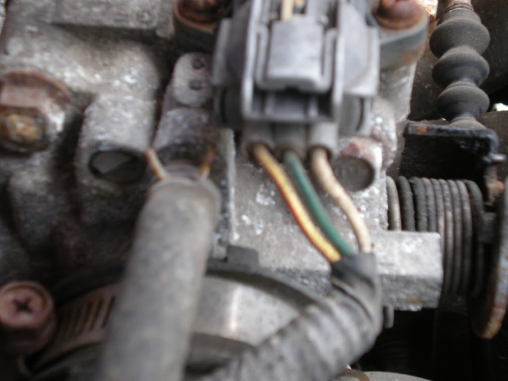
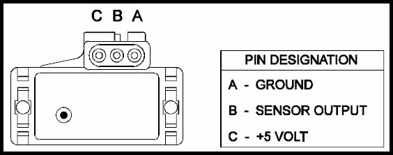
The MAP sensor typically has three wires:
- Signal Wire: This wire carries the voltage signal generated by the sensor to the ECU. It is often a colored wire, such as green or blue, and is connected to a specific pin on the ECU connector.
- Ground Wire: This wire connects the sensor to the vehicle’s ground system, ensuring a stable reference point for the voltage signal. It is usually a black wire and connects to the ECU ground or a dedicated ground point on the engine harness.
- Reference Voltage Wire: This wire supplies a reference voltage to the sensor, enabling it to function correctly. It is typically a red wire and connects to a +5V source from the ECU.
Decoding the Wiring Diagram
The wiring diagram for the MAP sensor is essential for understanding its connection to the ECU and other components. The diagram, usually found in the vehicle’s service manual or online resources, will illustrate the wire colors, pin locations, and connection points.
To interpret the diagram, follow these steps:
- Identify the MAP Sensor: Locate the MAP sensor on the intake manifold and note its location.
- Identify the Sensor Wires: Trace the wires from the sensor and note their colors.
- Locate the ECU Connector: Find the ECU connector, typically located under the dash or in the engine bay.
- Match Wire Colors to Pins: Use the wiring diagram to identify the corresponding pin numbers on the ECU connector for each wire color.
- Confirm Ground Connection: Ensure the ground wire is securely connected to a proper ground point.
- Verify Reference Voltage: Check that the reference voltage wire is connected to the +5V source on the ECU.
Troubleshooting Common MAP Sensor Wiring Issues
A faulty MAP sensor or wiring problem can lead to various engine performance issues, including:
- Rough Idle: A faulty MAP sensor can cause erratic idle speed due to incorrect fuel delivery and ignition timing.
- Stalling: A malfunctioning MAP sensor might lead to engine stalling, particularly under certain load conditions.
- Poor Acceleration: A faulty sensor can result in sluggish acceleration due to incorrect fuel delivery.
- Check Engine Light (CEL): The ECU will typically illuminate the CEL if it detects a fault with the MAP sensor or its wiring.
To diagnose potential wiring problems, perform the following checks:
- Visual Inspection: Examine the wiring for any signs of damage, chafing, or corrosion.
- Continuity Test: Use a multimeter to check for continuity between the MAP sensor and the ECU connector.
- Voltage Test: Measure the voltage at the reference voltage wire to ensure it is receiving the correct +5V supply.
- Ground Test: Verify that the ground wire has a good connection to the ground system.
- Signal Test: Use a multimeter to measure the voltage signal from the MAP sensor under varying engine conditions.
Common FAQs Regarding Honda B-Series MAP Sensor Wiring
Q: What are the symptoms of a faulty MAP sensor or wiring issue?
A: Symptoms can include rough idle, stalling, poor acceleration, and a Check Engine Light (CEL).
Q: How can I test the MAP sensor itself?
A: You can test the sensor using a vacuum pump and a multimeter to measure the output voltage under varying pressure conditions.
Q: Can I replace the MAP sensor myself?
A: Yes, replacing the MAP sensor is a relatively simple DIY task. However, it’s essential to ensure you have the correct replacement sensor and follow the proper installation procedures.
Q: What are some common causes of MAP sensor wiring problems?
A: Common causes include chafed wires, corroded connectors, loose connections, and broken wires.
Q: How can I prevent MAP sensor wiring issues?
A: Regular visual inspections of the wiring, proper routing and securing of the harness, and avoiding harsh chemicals or excessive heat near the sensor can help prevent wiring problems.
Tips for Maintaining MAP Sensor Wiring
- Regularly inspect the wiring: Look for any signs of damage, chafing, or corrosion.
- Securely route the wiring: Ensure the harness is properly routed and secured to prevent chafing or stress on the wires.
- Avoid harsh chemicals: Do not use harsh chemicals or solvents near the MAP sensor or wiring.
- Keep the engine bay clean: Regularly clean the engine bay to prevent dirt and debris from accumulating on the sensor and wiring.
- Use high-quality parts: When replacing the MAP sensor or its wiring, use high-quality components to ensure longevity and reliability.
Conclusion
The MAP sensor and its wiring are integral to the proper operation of the Honda B-Series engine. Understanding the wiring, diagnosing potential issues, and implementing preventative measures are crucial for ensuring optimal engine performance and longevity. By following the steps outlined in this guide, B-Series enthusiasts can confidently navigate the complexities of MAP sensor wiring, ensuring their engines run smoothly and efficiently.


Closure
Thus, we hope this article has provided valuable insights into Deciphering the Honda B-Series MAP Sensor Wiring: A Comprehensive Guide. We thank you for taking the time to read this article. See you in our next article!